
Airbus A320 Flight Control Surfaces Working Principle
A. General
The roll and pitch controls of the aircraft are electrical. They are based on two different types of digital computers (ELAC and SEC), each of them being able to control the aircraft in both axes. Monitoring and redundancy within the flight control system, aircraft sensors, power and hydraulic generation ensure a high degree of availability of the electrical control. The basic yaw control is hydromechanical as well as the alternate horizontal stabilizer control, thus providing the ability to keep the aircraft in flight during a temporary complete loss of electrical power. However, in normal conditions, some rudder control functions (trim, travel limitation) are achieved by the FAC.


B.
The normal pitch control law is basically the closed loop control of the load factor, and includes flight envelope protections. The normal lateral control law combines the roll rate control, turn coordination and Dutch roll damping functions.
The normal pitch control law is basically the closed loop control of the load factor, and includes flight envelope protections. The normal lateral control law combines the roll rate control, turn coordination and Dutch roll damping functions.
C. Ailerons
The roll control of the aircraft is achieved by one wing tip aileron augmented by four spoilers on each wing. The ailerons are manually controlled from the side stick controllers or automatically in autopilot function.
Each aileron can be powered by two servocontrols signalled by two Elevator and Aileron Computers (ELAC) and supplied from different hydraulic systems. In normal operation, the roll function of the ailerons is achieved through the ELAC 1 and the associated servocontrols in active mode, the ELAC 2 being in standby and its associated servocontrols in damping mode. In the event of a failure, the ailerons become automatically controlled by the ELAC 2 (roll) and the associated servocontrols switched to the active mode, the others being now damped. If a multiple failure condition causes the loss of the control of the two servocontrols of an aileron, the servocontrols automatically switch to the damping mode. This operating mode is also automatically engaged in the event of loss of pressure.
Two independent side stick controllers are installed in the cockpit. They include the roll and pitch position transducers and feel mechanisms, and a solenoid-operated detent that locks the control lever in neutral position when the autopilot is engaged.
D. Rudder
The rudder mainly permits to achieve the yaw control.
The rudder is actuated by three servo controls.
The servo controls can be driven:
- in manual mode:
either mechanically from the pedals ,
or electrically from the side stick and/or the rudder pedals
- in autopilot control mode:
from the FMGECs.
The rudder is powered by three servo controls mechanically signalled from the pedals through a single load path linkage fitted with a centering spring device that holds the servocontrol input in the neutral position if a disconnection occurs.
Each set of pedals is fitted with a position transducer.
Feel is provided by a spring rod, the zero force position of which is controlled by an electrical trim actuator.
A solenoid-operated mechanism increases the feel force threshold when the autopilot is engaged.
Two yaw-damper electrohydraulic servoactuators connected to a common output lever drive the linkage through a differential lever arrangement.
One servoactuator is normally operating, the other being by-passed. A spring rod is provided to center the actuators when both of them are depressurized.
The maximum control stroke is restricted by the Travel Limitation Unit as a function of the airspeed.
The trim actuator, the yaw damper servoactuators and the travel limitation unit are normally controlled by the Flight Augmentation Computer (FAC) 1, the FAC 2 being in standby.
In addition to their basic function, the trim actuator and the yaw damper servoactuators are used to introduce the autopilot signals.
Rudder immobilization or runaway in the event of a servocontrol valve jamming is prevented by a spring rod and pressure relief valve arrangement.
E. Elevators (Ref. 27-30 and 27-90)
The pitch control of the aircraft is achieved by two mechanically independent elevators controlled manually from the side stick controllers or automatically in autopilot function.
Each elevator can be driven by two electrohydraulic servocontrols signalled by the ELACs or SEC 1 or 2, and supplied from different hydraulic systems.
In normal operation the elevators are controlled by the ELAC 2 and the associated servocontrols in active mode, the other computers being in standby and the servocontrols in damping mode. In the event of a high load-factor demand that would cause one servocontrol to stall, the second servocontrol is operated. In the event of failure, the elevators are controled by ELAC1, then by SEC2 or SEC1. In the event of the loss of control of the two servocontrols of the elevator, the servocontrols are automatically switched to a centering mode and hold the surface in the neutral position (Electrical control loss). In the event of the loss of the two hydraulic systems supplying the servocontrols of one elevator, the damping mode becomes automatically engaged.
The side stick controller operation for the pitch control is similar to the roll control as described in para. 1.B.
F. Trimmable Horizontal Stabilizer (Ref. 27-40 and 27-90)
The pitch trim function is achieved by the Trimmable Horizontal Stabilizer (THS) either automatically in normal in-flight manual mode or autopilot function or manually from the handwheels in normal ground operation or in-flight failure condition.
The THS is moved and held by a THS actuator that includes a double load-path ball screw powered by two differentially coupled hydraulic motors mechanically servocontrolled. The ball screw is fitted with a no-back brake, the motors are fitted with pressure-off brakes. The control loops include a device that applies both pressure-off brakes in the event of either control valve jamming.
The input shaft of the THS actuator is normally driven by an electrical motor servocontrolled by the ELAC 2, two other motors controlled respectively by ELAC 1 or SEC 1 and SEC 2.
The input shaft of the THS actuator can also be manually driven by the pilots through a mechanical linkage normally moved by the handwheels.
An overriding mechanism gives the priority to the mechanical control over the electrical control.
G. Spoilers
Five spoiler surfaces are provided on each wing to achieve the functions below :
Each surface is controlled by one servocontrol supplied from the Green, Yellow or Blue system and signalled from the SEC 1, 2 or 3.
The combination of the different functions is achieved in the computers.
In the event of an electrical failure, the associated surface is hydraulically held down. In the event of a hydraulic failure, the servocontrol is hydraulically locked in one direction to prevent the surface from raising. In both cases the control of the symmetrical surface is automatically inhibited.
Five spoiler surfaces are provided on each wing to achieve the functions below :
- roll spoiler (surfaces 2 to 5)
- speedbrake (surfaces 2 to 4)
- ground spoilers (all surfaces).
Each surface is controlled by one servocontrol supplied from the Green, Yellow or Blue system and signalled from the SEC 1, 2 or 3.
The combination of the different functions is achieved in the computers.
In the event of an electrical failure, the associated surface is hydraulically held down. In the event of a hydraulic failure, the servocontrol is hydraulically locked in one direction to prevent the surface from raising. In both cases the control of the symmetrical surface is automatically inhibited.
H. Electrical Flight Control System
(1) General The Electrical Flight Control System includes the ELACs, the SECs, the Flight Control Data Concentrators (FCDCs) and vertical accelerometers.
The EFCS is built according to the principles below :
The EFCS is built according to the principles below :
(a) Redundancy and dissimilarity
The EFCS includes two ELACs, three SECs, two FCDCs and four accelerometers. The ELACs and SECs are both able to achieve the roll and pitch control of the aircraft. These two types of computer differ by their internal architecture, hardware, type of microprocessor, software. For each computer type, the control and monitoring software are different.
The EFCS includes two ELACs, three SECs, two FCDCs and four accelerometers. The ELACs and SECs are both able to achieve the roll and pitch control of the aircraft. These two types of computer differ by their internal architecture, hardware, type of microprocessor, software. For each computer type, the control and monitoring software are different.
(b) Monitoring
The monitoring of each computer (ELAC, SEC) is achieved as follows:
The monitoring of each computer (ELAC, SEC) is achieved as follows:
- Monitoring channel: Each computer consists of two physically and electrically-separated channels, one being dedicated to the control functions, the other to the monitoring of these. These two channels perform the actuator command signal computation using different digital processes. The monitoring channel permanently compares the results of these computations and inhibits the signal to the actuator, should a discrepancy occur.
- Self-monitoring capacity : Each channel is able to detect the failure of the critical signals it receives or emits and to detect internal failures by test of the processor and monitoring of its internal power supply.
- Cross-talk : Each control and associated monitoring channel permanently exchanges information via digital buses, therefore consolidating and validating information received from different sensors.
- Automatic power-on and pressure-on safety tests performed without movement of the surfaces.
(c) Installation
The installation takes into account the principles below :
The installation takes into account the principles below :
- Wiring installation : specific connectors are used for the EFCS.
Electrical routes 1 are used for items powered from the emergency electrical supply, routes 2 are used for items powered from the normal electrical supply.
Control signals are routed in routes S, monitoring signals are routed in routes M. In the sections exposed to the engine burst the EFCS cables are shared between the normal and deviated routes. - Protection against lightning strikes : in the exposed areas the wires are installed in metal shields - for each signal the wires are twisted. The grounding of signals is not achieved in the exposed areas. Aileron-related wires are routed in the leading edge whereas spoiler-related wires are in the trailing edge. The inputs of the computers include low-pass filters and overvoltage protections if the associated wires are routed in exposed areas.
(2) Control laws
The different control laws and associated protections, as listed below may be used, depending on the integrity of the flight control and flight augmentation systems and their peripherals. They are implemented in the computer.
The different control laws and associated protections, as listed below may be used, depending on the integrity of the flight control and flight augmentation systems and their peripherals. They are implemented in the computer.
(3) Roll and yaw controls :
(a) Roll normal law
This is the combined control of the ailerons, spoiler surfaces 2 to 5 and rudder from the side stick controllers coupled according to the priority logic. In flight, it achieves the control and the limitation of the roll rate, providing a neutral spiral stability up to 33 degrees of bank angle, the turn coordination and the dutch roll damping. It requires gains depending on the ground/flight condition, airspeed and configuration. On the ground it provides a fixed relationship between the side stick controller angle and the aileron and spoiler deflections. The rudder can also be directly controlled either mechanically from the pedals or from the trim switches. The rudder deflection is limited as a function of the airspeed.
This is the combined control of the ailerons, spoiler surfaces 2 to 5 and rudder from the side stick controllers coupled according to the priority logic. In flight, it achieves the control and the limitation of the roll rate, providing a neutral spiral stability up to 33 degrees of bank angle, the turn coordination and the dutch roll damping. It requires gains depending on the ground/flight condition, airspeed and configuration. On the ground it provides a fixed relationship between the side stick controller angle and the aileron and spoiler deflections. The rudder can also be directly controlled either mechanically from the pedals or from the trim switches. The rudder deflection is limited as a function of the airspeed.
(b) Roll direct law
This is the control of the aileron and spoiler surfaces 2 to 5 from the side stick controllers coupled according to the priority logic.
It achieves the control of the above surface angles using gains depending on the configuration.
This is the control of the aileron and spoiler surfaces 2 to 5 from the side stick controllers coupled according to the priority logic.
It achieves the control of the above surface angles using gains depending on the configuration.
(c) Alternate yaw control
This is the direct control of the rudder from the pedals or the trim switches complemented by a limited-authority dutch-roll damping function using gains depending on the configuration. The rudder deflection is limited as a function of the airspeed.
This is the direct control of the rudder from the pedals or the trim switches complemented by a limited-authority dutch-roll damping function using gains depending on the configuration. The rudder deflection is limited as a function of the airspeed.
(4) Pitch control
(a) Pitch normal law
This is the combined control of the elevators and THS from the side stick controllers coupled according to the priority logic to achieve the load factor control. It requires load factor and pitch attitude rate feedbacks, variable gains depending on ground/flight condition, radio altimeters, airspeed and configuration. It includes a high angle-of-attack protection and a load factor limitation that cannot be overriden by the crew, and an overspeed protection.
On the ground, it provides a fixed relationship between the side stick controller angle and the elevator deflections.
(b) Pitch alternate law
This is the control of the elevators and the THS, if operative, from the side stick controllers coupled according to the priority logic to achieve the load factor control.
It uses limited authority load factor and pitch rate feedbacks and gains depending on the configuration. It includes a load factor limitation that cannot be overriden by the crew and alternate protections.
(c) Pitch direct law
This is the control of the elevator angle from the side stick controllers coupled according to the priority logic with a gain depending on the configuration. Pitch trim can be achieved via the mechanical control of the THS.
This is the control of the elevator angle from the side stick controllers coupled according to the priority logic with a gain depending on the configuration. Pitch trim can be achieved via the mechanical control of the THS.
(5) Speedbrake control
This is the control of the position of the spoiler surfaces 2 to 4 from the speedbrake control lever.
This is the control of the position of the spoiler surfaces 2 to 4 from the speedbrake control lever.
(6) Ground spoiler control
This is the automatic full deployment of all the spoiler surfaces at touch down.
This is the automatic full deployment of all the spoiler surfaces at touch down.
(7) Description of Flap and Slat Control
(a) Flap Control
Achieved on each wing by one inboard flap and one outboard flap.
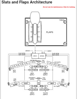
Achieved on each wing by one inboard flap and one outboard flap.

(b) Slat Control Lift Augmenting
Achieved on each wing by five slats.
Achieved on each wing by five slats.
Reviewed by Rabindar Singh on Apr 05 2019
Rating:
Credit : Rabindar Singh
Sharing is Caring & Helping


Post a Comment
Spam Not Allowed. We accepting Guest Posts. Any Doubts write us mail@kasworld-aero.ml